Mechanics of Solids - short answer type questions from AMIE exams (Summer 2017)
Answer the following questions in brief (10 x 2)
State the difference between thin and thick cylinder.
Thin cylinder
- The cylinder which has a thickness is less than 1/10 to 1/20 of its diameter, that cylinder is called a thin cylinder.
- A cylinder whose wall thickness is less than 1/20 times of its internal diameter
- The thin cylinder is only resisted by internal pressure.
- Low stress consuming capacity.
Thick cylinder
- The cylinder which has a thickness is more than 1/20 of its diameter that cylinder is called a thick Cylinder.
- A cylinder whose wall thickness is greater than 1/20 times its internal diameter.
- The thick cylinder is resisted by internal as well as external pressure.
- More stress consuming capacity.
What are sagging and hogging bending moments?
The bending moment at a section is considered positive if the bending moment at that section is such that it tends to bend the beam to a curvature having concavity at the top.

Similarly the bending moment (B.M.) at a section is considered negative if the bending moment at that section is such that it tends to bend the beam to a curvature having convexity at the top. The positive B.M. is often called sagging moment and negative B.M. as hogging moment.
What is a spring? What are their types and applications?
Springs are the elastic bodies which absorb energy due to resilience. The absorbed energy may be released as and when required. A spring which is capable of absorbing the greatest amount of energy for the given stress, without getting permanently distorted, is known as the best spring. The two important types of springs are:
- Laminated or leaf springs and
- Helical springs.
Leaf springs
The laminated or leaf spring (also known as flat spring or carriage spring) consists of a number of flat plates (known as leaves) of varying lengths held together by means of clamps and bolts, as shown in the figure.
 |
| Leaf spring |
These are mostly used in automobiles. The major stresses produced in leaf springs are tensile and compressive stresses.
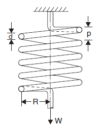
Helical Springs
Helical springs are the thick spring wires coiled into a helix.
They are of two types: (i) close coiled helical spring (ii) open coiled helical spring.
Close-coiled helical springs: Close-coiled helical springs are the springs in which the helix angle is very small or in other words the pitch between two adjacent turns is small.


where
d = Diameter of spring wire
p = Pitch of the helical spring
n = Number of coils
R = Mean radius of spring coil
W = Axial load on spring
C = Modulus of rigidity
τ = Max. shear stress induced in the wire
θ = Angle of twist in spring wire, and
δ = Deflection of spring due to axial load
l = Length of wire.
Define modulus of resilience.
Resilience
This may be defined as the property of a metal by virtue of which it stores energy and resists shocks or impacts. It is measured by the amount of energy absorbed per unit volume, in stressing a material up to the elastic limit.
Modulus of resilience
The maximum energy which can be stored in a body up to the elastic limit is termed proof resilience.
Proof resilience per unit volume is termed as a modulus of resilience. Obviously, the energy stored per unit volume at the elastic limit is the modulus of resilience.
The annealed copper is not used for springs due to its very low elastic limit. However, the cold-worked
copper has a much high elastic limit (and resilience) and therefore it is used for springs. This shows that resilience is associated with a high elastic limit. We may note that resilience is of importance for materials required to bear shocks and vibrations.
Differentiate between modulus of elasticity and modulus of rigidity.
Torsional Rigidity
Torsional rigidity is the resistance against torsional deformation. Or the minimum force required to deform the object by twisting. It is the product of modulus of rigidity(G) and polar moment of inertia (J), denoted by k, having S.I. Units N.m2
It is given by

Modulus of rigidity
The ratio of tensile stress or compressive stress to the corresponding strain is constant. This ratio is known as Young’s Modulus or Modulus of Elasticity or modulus of rigidity and is denoted by E.
E = stress/strain = σ/e
State principle of superposition
Principle of Superposition. When a number of loads are acting on a body, the resulting strain, according to the principle of superposition, will be the algebraic sum of strains caused by individual loads.
Define the term bending moment and shear force.
Shear force
The algebraic sum of the vertical forces at any section of a beam to the right or left of the section is known as shear force. It is briefly written as S.F.
Bending moment
The algebraic sum of the moments of all the forces acting to the right or left of the section is known as the bending moment. It is written as B.M.
What assumptions are taken in the analysis of shear stresses in beams?
- For all values of y, q is uniform across the width of a section of any shape which is not correct for all shapes of the section.
- F = dM/dx is derived from the assumption that the bending stress varies linearly across the depth of section and zero at the centroid.
- The material is homogeneous and isotropic.
- The material has the same value of E (Young's Modulus of Elasticity) in tension and compression.
State the limitation of governing differential equation of beams.
Beam theory is founded on the following two key assumptions known as the Euler-Bernoulli assumptions:
- Cross-sections of the beam do not deform in a significant manner under the application of transverse or axial loads and can be assumed as rigid. The cross-section can only undergo a rigid-body motion in its plane, i.e. two rigid body translations and one rotation. Also assumed that there is no rotation of the cross-section around the e₃ axis.
- During deformation, the cross-section of the beam is assumed to remain planar and normal to the deformed axis of the beam. The cross-section can only translate rigidly in the axial direction or rotate with respect to the e₂ and e₃ axes by angles θ₂ and θ₃, respectively


Define torsional moment of resistance.
The strength of a shaft means the maximum torque or maximum power the shaft can transmit.
Torsional rigidity or stiffness of the shaft is defined as the product of modulus of rigidity (C) and polar moment of inertia of the shaft (J). Hence mathematically, the torsional rigidity is given as,
Torsional rigidity = C × J = TL/θ
Torsional rigidity is also defined as the torque required to produce a twist of one radian per unit length of the shaft.
An important torsion equation for a circular solid shaft is

where
R = Radius of shaft
L = Length of shaft
T = Torque applied at the end BB
τ = Shear stress-induced at the surface of the shaft due to torque T
C = Modulus of rigidity of the material of the shaft
---
- The study material for AMIE/B Tech/Junior Engineer exams is available at https://amiestudycircle.com
- If you like the post please share your thoughts in the comment section


Comments