Principles of Geoinformatics - short answer type questions from AMIE exams (Summer 2020)
Differentiate between the following (2x 10)
Permanent benchmark and temporary benchmark
Permanent Bench Marks These bench marks are established between G.T.S. bench marks by the Survey of India or other government agencies such as P.W.D., on clearly defined and permanent natural or cultural detail points such as isolated rocks culverts, kilometre stones, railway platforms, gate pillars of inspections houses, etc.
Temporary Bench Marks These are the reference points on which a day’s work is closed and from where levelling is continued next day in the absence of a permanent B.M. Their elevations are referred to as the reduced levels. Such bench marks should be carefully established on permanent detail points such as km stones, parapets, floor of verandahs, roots of old trees, etc. Their correct descriptions should invariably be written in level books.
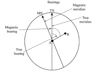
True and magnetic bearing
True Bearing. The horizontal angle between the true meridian and the survey line measured in a clockwise direction, is called true bearing of the line.
Magnetic Bearing. The horizontal angle which a survey line makes with the magnetic meridian, is called magnetic bearing. It is not constant at a point but varies with laps of time.
Curvature and refraction effects
Effect of curvature. The effect of the curvature on a staff reading, is equal to the distance between the points where the line of sight and level line through the level, intersects the staff. The correction for curvature is, therefore, negative and is always subtracted from the staff reading.
Effect of refraction. The line of sight provided by a level does not remain straight. It gets bent towards the earth due to refraction as it passes through layers of air of different densities. The effect of refraction is therefore opposite to that of curvature and the points appear higher than what they really are. The correction of refraction is always added to the staff readings.
Radiation and resection
Radiation Method. In this method, a plane table is set up at any commanding station. Detail points are plotted on their radiating lines drawn from the location of the instrument station, after reducing their respective ground distances on the desired scale of survey. This method is suitable for the survey of small areas which can be commanded from a single station.
Resection Method. The process of determining the location of the station occupied by the plane table, by means of drawing rays from stations whose locations have already been plotted on the sheet, is called resection.
Accuracy and precision
To surveyors, “accuracy” refers to how closely a measurement or observation comes to measuring a "true value," since measurements and observations are always subject to error. “Precision” refers to how closely repeated measurements or observations come to duplicating measured or observed values.
Compound and reverse curve
Compound curve A curve which consists of two or more arcs of different circles with different radii having their centres on the same side of the common tangent in succession, each bending in the same direction, is known as a compound curve.


Horizontal and vertical curve
Horizontal Curves. Horizontal curves are provided to change the direction or alignment of a road. Horizontal Curve are circular curves or circular arcs. The sharpness of a curve increases as the radius is decrease which makes it risky and dangerous. The main design criterion of a horizontal curve is the provision of an adequate safe stopping sight distance. These may be further classified as : (i) Simple (ii) Compound (iii) Reverse (iv) Transition.
Vertical Curves. Vertical curves are provided to change the slope in the road and may or may not. be symmetrical. They are parabolic and not circular like horizontal curves. Identifying the proper grade and the safe passing sight distance is the main design criterion of the vertical curve, iln crest vertical curve the length should be enough to provide safe stopping sight distance and in sag vertical curve the length is important as it influences the factors such as headlight sight distance, rider comfort and drainage requirements.

Tip and tilt
Tilt: It is the rotation of the aerial camera about the line of flight.
Tip: It is the rotation of the aerial camera about a horizontal axis normal to the line of flight. This is also known as swing.
Geodimeter and Tellurometer
Geodimeter. It consists of an electromagnetic optical instrumentation unit at one end of the line and an optical instrumentation unit at the other end of the line. The electromagnetic optical unit is known as the Geodimeter which transmits a highly collimated, electrically modulated light beam to the optical unit centred over the other end of the line. The optical unit consists of a reflecting element which returns the light beam to the Geodimeter. A comparison is made between the light beam returned to the Geodimeter and the one transmitted by the Geodimeter. From the comparison, for two or three separately used modulating frequencies, the distance between the two instrument stations can be determined.

Tellurometer. The main principle of working of this instrument is similar to that of the Geodimeter with the exception that in it high-frequency radio waves (microwaves) are used instead of light waves. With this modification, tellurometers can be used during the day and night and even in hazy weather, whereas the Geodimeters are used at nights only.

Aerial photography and satellite image
Aerial photograph. These are the photographs obtained as a result of photography of ground from
the air with a camera mounted on an aircraft. The image of the ground photographed is formed on the focal plane of the camera’s objective, where a sensitive film is placed.
Satellite image. Satellite images are exclusively digital and are taken using a series of electronic scanners incorporated in satellites that orbit the Earth. Satellites generally operate at altitudes greater than 20,000 metres, resulting in much wider angle shots with less detail than aerial photos.
---
- The study material for AMIE/B Tech/Junior Engineer exams is available at https://amiestudycircle.com
- If you like the post please share your thoughts in the comment section


Comments