Manufacturing Automation - short answer questions from AMIE exams (Summer 2019)
Geneva Mechanism
The Geneva drive or Maltese cross is a gear mechanism that translates a continuous rotation movement into intermittent rotary motion.
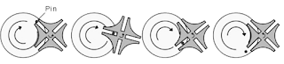
The rotating drive wheel is usually equipped with a pin that reaches into a slot located in the other wheel (driven wheel) that advances it by one step at a time. The drive wheel also has an elevated circular blocking disc that "locks" the rotating driven wheel in position between steps.
Detroit type automation
- When companies began to replace scrapped or obsolete bine with those employing the latest technological advances, gave Up what eventually became known as Detroit automation, e.g. inline sequencing of manufacturing operations that utilized automatic material handling techniques.
- Automation transformed the automobile industry. Sequences of different machining operations could be carried out on a single platform and to higher tolerances and higher speeds than previous.
- Detroit automation has started from the automobile industry.
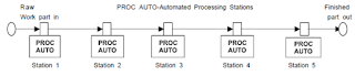
- An automated flow line consists of several machines or workstations which are linked together by work handling devices that transfer parts between the stations. The transfer of work parts occurs automatically and the workstations carry out their specialized functions automatically.
- The flow line can be symbolized as shown in the following figure.
How do you specify a Robot?
Every industrial robot is defined by certain measurements, payload, and design features.
Axis Movement Specifications:
- Axes
- Robot Motion
- Robot Motion
Robot Specifications for Weight
- Payload
- Robot
Specifications and Work Envelope
- Vertical Reach
- Horizontal
Application of machine vision systems in the industry
- Object Detection
- Parts Counting
- Surface Defect Identification
- Print Defect Identification
- Print Character Reading
- Barcode Scanning
- Locating
- Measurement
- Robotic Guidance
What is a flexible manufacturing cell?
A flexible manufacturing system (FMS) is a production method that is designed to easily adapt to changes in the type and quantity of the product being manufactured. The flexible manufacturing cell consists of one or several CNC machine tools or machining centres. The unit can automatically change tools and fixtures as needed to machine different workpieces.
Use of AGVs in automation
AGVs provide automated material movement for a variety of industries including:
- Automotive
- Beverage
- Chemicals
- Commercial printing
- Food
- Hospital
- Manufacturing
- Newspaper
- Paper
- Pharmaceutical
- Plastics
- Warehousing and distribution
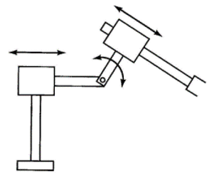
Show the LRL robot arm configuration.
Difference between inspections and testing.
- Product testing, often known as lab testing, typically involves testing a product against a specific standard or regulation in a certified laboratory. Whereas product inspection often involves checking a random sample of an order for compliance with a buyer’s requirements and specifications.
- Product inspection is the process of checking goods for compliance with your specifications and requirements. Generally conducted at the factory manufacturing your product, the product inspection process primarily focuses on checking the appearance, construction and basic function of a product. The other key purpose of product inspection is to help you identify and address any quality defects in your products before they reach your customers.
Linear and rotary type transfer mechanisms
Linear transfer mechanisms
- Walking beam systems With the walking beam transfer mechanism, the work parts are lifted up from their workstation locations by a transfer bar and moved one position ahead to the next station. The transfer bar then lowers the parts into nests which position them more accurately for processing.
- Chain-drive conveyor system Either a chain or a flexible steel belt is used to transport the work carriers. The chain is driven by pulleys in either an over and under configuration, in which the pulleys turn about a horizontal axis, or around the corner configuration, in which the pulleys rotate about a vertical axis. This general type of transfer system can be used for continuous, intermittent, or non-synchronous movement of work parts.
- Rack and Pinion This mechanism is simple but is not considered especially suited to the high-speed operation often associated with indexing machines. The device uses a piston to drive the rack, which causes the pinion gear and attached indexing table to rotate.
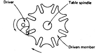
- Geneva Mechanism The two previous mechanisms convert a linear motion into a rotational motion. The Geneva mechanism uses a continuously rotating driver to index the table, as pictured in Figure. If the driven member has six slots for a six-station dial indexing machine, each turn of the driver will cause the table to advance one-sixth of a turn. The driver only causes movement of the table through a portion of its rotation. For a six-slotted driven member, 120° of a complete rotation of the driver is used to index the table. The other 240° is dwell. For a four slotted driven member, the ratio would be 90° for index and 270° for dwell. The usual number of indexing per revolution of the table is four, five, six, and eight.
Absolute and incremental dimensioning in the NC system.
- In absolute programming, all coordinate values are relative to a fixed origin of the coordinate system. Axis movement in the positive direction does not require inclusion of the sign; while negative movements do require signs.
- In incremental systems, every measurement refers to a previously dimensioned position (point-to-point). Incremental dimensions are the distances between two adjacent points.
---
- The study material for AMIE/B Tech/Junior Engineer exams is available at https://amiestudycircle.com
- If you like the post please share your thoughts in the comment section


Comments